By Matthew Hand
Product Line Specialist
Thomson Industries, Inc.
www.thomsonlinear.com, thomson@thomsonlinear.com
When machine designers need fast, accurate control over the linear movement of the heaviest loads, they typically choose profile rail linear guides over round rail guides. Profile rails, sometimes called square rails, offer increased rigidity and stiffness over round rail products, as well as high load capacity in a small package. But profile rails can differ significantly in rigidity, load capacity, travel accuracy, smoothness of operation, speed, and come in various sizes and mounting configurations.
Architectural options
Profile rail architectures vary mostly in the shape and arrangement of the rolling elements. The primary options are: double back architecture with ball bearings, double back architecture with roller bearings and double face architecture with ball bearings.
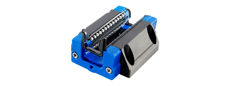
- The double-back with ball bearings architecture, uses two sets of ball bearings running back to back inside of the rail, providing high moment load capacity. The ball track groove is only slightly larger in radii than that of the balls themselves, which cradles the ball bearings as they infinitesimally flatten under load, slightly expanding the contact area between the balls and the races.

Figure 1: Double backarchitecture with bearings
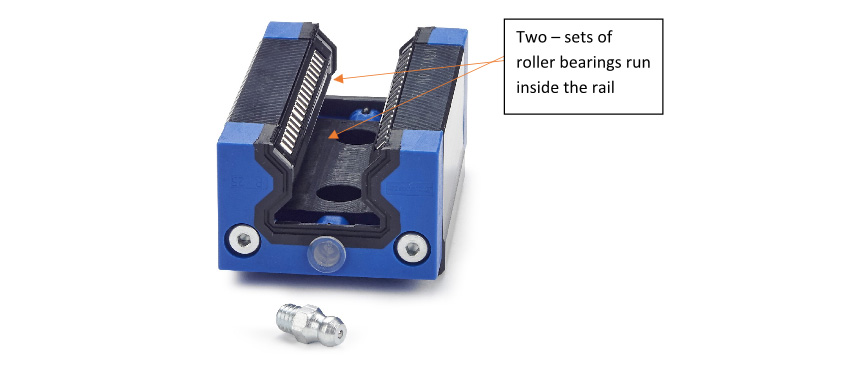
- In the double back with rollers option, cylindrical rollers replace ball bearings, (Figure 2). This provides even greater stability over the convex balls, which have but a single point contact area, making them slightly more vulnerable to deformation under pressure.

Figure 2: Double-backed architecture, with rollers
- With the double face architecture with ball bearings, rails are much more tolerant of mounting surface inaccuracies, but compromise rigidity and moment load capacity. It uses four bearing tracks, which are deployed face to face on the top of the rail, rather than inside of it (Figure 3). The double-faced bearing arrangement results in equal load-carrying capacity in all directions.

Figure 3: Double faced architecture, with ball bearings
Choosing which architecture is right for which application requires balancing tradeoffs in the areas of rigidity, capacity, accuracy, smoothness, size, durability and cost. Other profile architectures do exist but this article is focusing on the industry leaders.
Exploring the tradeoffs
Choice of bearing architecture begins with a preliminary determination of the following information:
- The mass of the load
- The location of the load, e.g. placed on top of the carriage or to the side
- Required accuracy
- Desired travel life
- System mounting constraints
The rigidity, load bearing capacity, and tracking accuracy of the double backed architectures, make them ideal for demanding applications including high load industrial automation, machine tool equipment and precision measuring.
For the most demanding of applications, the roller bearing elements would offer even greater advantage. The rollers are more space efficient, which means they can deliver higher load capacity in a smaller footprint, which may be of value in tight quarters.
Many factors affect the costs and the design of a linear guide. For applications requiring the highest rigidity, motion engineers typically specify the double back architecture, using either ball bearings or roller bearings. For applications requiring less rigidity, they might specify what is called double face architecture, which might also be used with either ball or roller bearings. But these might not apply in all situations.
Although, the double backed architectures might, for example be the best high precision, high capacity applications, the double-faced architectures might be better for applications where smooth operation and cost are drivers. There are also ways to configure both these architectures to make them more rigid as well as smoother.
It all comes back to determining what is the intended load and where it will be placed. There are also many selection tools that guide in the selection of the configurations to meet customer needs. Thomson, for example, provides tools that calculate application numbers through a comprehensive set of algorithms and compares results to a database of available technology to determine an optimized solution set.
To further assist design engineers in making the right choices, device vendors such as Thomson, provide design resources, including teams of application engineers who assist in identifying the optimal solution, technical collateral, white papers, webinars and video instruction.
With so many options available, the final choice comes down to the engineers’ judgment and their reading of their customer’s preferences – stated and unstated – which will result in the final design.


